| |
|
|
|
TDS2012C
|
TDS2014C
|
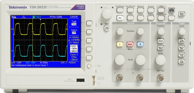
TDS2022C
|
TDS2024C
|
|
Display (QVGA LCD)
|
TFT
|
TFT
|
TFT
|
TFT
|
TFT
|
TFT
|
TFT
|
|
Bandwidth*3
|
50 MHz
|
70 MHz
|
70 MHz
|
100 MHz
|
100 MHz
|
200 MHz
|
200 MHz
|
|
Channels
|
2
|
2
|
4
|
2
|
4
|
2
|
4
|
|
External Trigger Input
|
Included on all models
|
|
Sample Rate on Each Channel
|
500 MS/s
|
1.0 GS/s
|
1.0 GS/s
|
2.0 GS/s
|
2.0 GS/s
|
2.0 GS/s
|
2.0 GS/s
|
|
Record Length
|
2.5k points at all time bases on all models
|
|
Vertical Resolution
|
8 bits
|
|
Vertical Sensitivity
|
2 mV to 5 V/div on all models with calibrated fine adjustment
|
|
DC Vertical Accuracy
|
±3% on all models
|
|
Vertical Zoom
|
Vertically expand or compress a live or stopped waveform
|
|
Maximum Input Voltage
|
300 VRMS CAT II; derated at 20 dB/decade above 100 kHz to 13 Vp-p AC at 3 MHz
|
|
Position Range
|
2 mV to 200 mV/div +2 V
>200 mV to 5 V/div +50 V
|
|
Bandwidth Limit
|
20 MHz for all models
|
|
Input Coupling
|
AC, DC, GND on all models
|
|
Input Impedance
|
1 MΩ in parallel with 20 pF
|
|
Time Base Range
|
5 ns to 50 s/div
|
5 ns to 50 s/div
|
5 ns to 50 s/div
|
2.5 ns to 50 s/div
|
2.5 ns to 50 s/div
|
2.5 ns to 50 s/div
|
2.5 ns to 50 s/div
|
|
Time Base Accuracy
|
50 ppm
|
|
Horizontal Zoom
|
Horizontally expand or compress a live or stopped waveform
|
|
I/O Interfaces
|
|
USB Ports
|
USB host port on front panel supports USB flash drives
USB device port on back of instrument supports connection to PC and all PictBridge-compatible printers
|
|
GPIB
|
Optional
|
|
Nonvolatile Storage
|
|
Reference Waveform Display
|
(2) 2.5k point reference waveforms
|
|
Waveform Storage without USB Flash Drive
|
(2) 2.5k point
|
(2) 2.5k point
|
(4) 2.5k point
|
(2) 2.5k point
|
(4) 2.5k point
|
(2) 2.5k point
|
(4) 2.5k point
|
|
Maximum USB Flash Drive Size
|
64 GB
|
|
Waveform Storage with USB Flash Drive
|
96 or more reference waveforms per 8 MB
|
|
Setups without USB Flash Drive
|
10 front-panel setups
|
|
Setups with USB Flash Drive
|
4000 or more front-panel setups per 8 MB
|
|
Screen Images with USB Flash Drive
|
128 or more screen images per 8 MB (the number of images depends on file format selected)
|
|
Save All with USB Flash Drive
|
12 or more Save All operations per 8 MB
A single Save All operation creates 3 to 9 files (setup, image, plus one file for each displayed waveform)
|
*3 Bandwidth is 20 MHz at 2 mV/div, all models.
Acquisition Modes
|
Mode
|
Description
|
|
Peak Detect
|
High-frequency and random glitch capture. Captures glitches as narrow as 12 ns (typical) at all time base settings from 5 μs/div to 50 s/div
|
|
Sample
|
Sample data only
|
|
Average
|
Waveform averaged, selectable: 4, 16, 64, 128
|
|
Single Sequence
|
Use the Single Sequence button to capture a single triggered acquisition sequence
|
|
Roll
|
At acquisition time base settings of >100 ms/div
|
Trigger System
|
Characteristic
|
Description
|
|
Trigger Modes
|
Auto, Normal, Single Sequence
|
Trigger Types
|
Trigger
|
Description
|
|
Edge (Rising/Falling)
|
Conventional level-driven trigger. Positive or negative slope on any channel. Coupling selections: AC, DC, Noise Reject, HF Reject, LF Reject
|
|
Video
|
Trigger on all lines or individual lines, odd/even or all fields from composite video, or broadcast standards (NTSC, PAL, SECAM)
|
|
Pulse Width (or glitch)
|
Trigger on a pulse width less than, greater than, equal to, or not equal to, a selectable time limit ranging from 33 ns to 10 s
|
Trigger Source
|
Characteristic
|
Description
|
|
2-channel Models
|
CH1, CH2, Ext, Ext/5, AC Line
|
|
4-channel Models
|
CH1, CH2, CH3, CH4, Ext, Ext/5, AC Line
|
Trigger View
|
Displays trigger signal while Trigger View button is depressed.
|
Trigger Signal Frequency Readout
|
Provides a frequency readout of the trigger source.
|
Cursors
|
Characteristic
|
Description
|
|
Types
|
Amplitude, Time
|
|
Measurements
|
ΔT, 1/ΔT, ΔV
|
Automatic Waveform Measurements
|
Period, Frequency, +Width, –Width, Rise Time, Fall Time, Max, Min, Peak-to-Peak, Mean, RMS, Cycle RMS, Cursor RMS, Duty Cycle, Phase, Delay
|
Waveform Math
|
Characteristic
|
Description
|
|
Operators
|
Add, Subtract, Multiply, FFT
|
|
|
|
|
|
 Sofort versandfähig, ausreichende Stückzahl